
Speed’s 95” Twin Cam Kit Part 1
American IronPart 1: Bolting in the cams and closing up the gearcase
American Iron Magazine
June 2006, Issue 209
Continuing with our quest to show you what’s available for owners who want more power from their Twin Cam-powered bikes, here’s the latest 95” kit we’ve found that works very well. It’s from Speed’s Performance and it comes with matched heads, cams, pistons, and cylinders. The head honcho at Speed’s, a motorhead named Speed (you knew that was coming, didn’t you?), has been hopping up Harleys for over 40 years. Speed grew up around Harleys and his dad always had least one in the garage all stripped down and juiced up.
Though Speed has a shop located in Watertown, South Dakota, he does a lot of his hop-up work at events right in the back of his specially outfitted trailer. The box unit of this tractor-trailer rig is half dyno and half engine room. And that’s where we did this engine build during last year’s Biketoberfest. In truth, it’s and impressive operation, and two of Speed’s master engine builders, Jamie Hanson and Jimbo, were on hand to do the engine build we’re going to show you in this and the next issue.
This time around, Jamie and Jimbo are going to bolt in a set of Speed’s specially ground camshafts, which are fitted with an S&S Cycle gear drive kit. These cams have a .615” lift on the intakes and .585” on the exhausts, which means that the heads are also fitted with a special R&R Cycle valve spring combo. But we’ll get to the heads, pistons, and cylinders in the nest issue, when we bolt on those components. Suffice to say at this point that this kit promises output out around 105-112 hp if installed by a competent mechanic. However, Speed states that you can get 110 or so hp if you have a proficient tuner dial the engine in. Also, you must use a performance exhaust system, like a Hooker or a D&D 2-into-1 system, with this engine to get these results. But more on all that next month, which is when we’ll also have the dyno sheet for you.
Bolting in a set of cams is not the only change Speed makes in the lower end. He also checks the pinion shaft’s run-out before the build even starts. Speed wants no more than 0.002” run-out at the end of the shaft. More than that and there’s a problem with the lower end.
Speed then checks the oil pump by completely disassembling it and looking for any signs of scoring or any other damage. The oil pressure relief valve is also checked to make sure it’s operating smoothly. The valve is then modified to increase the engine’s oil pressure about 10 psi over its entire operating range. Of course, all the oil pump seals are changed, too.
Lastly, once the gear-driven cams are installed, the way the gears mesh is checked to make sure that they do not engage too tightly or too loosely. Too tight will cause the engine to whine, while too loose will cause a clatter. That said, check out the accompanying photos to see how Jamie and Jimbo bolted up the lower end of this Twin Cam motor.
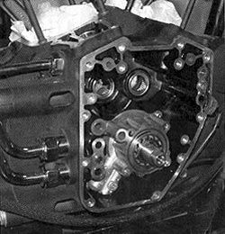
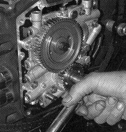
1. Our opening shot shows the engine stripped down and ready for its new performance kit. The oil pump has been reinstalled and the inner cam bearings have been replaced.
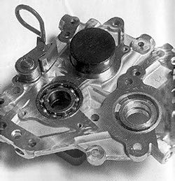
2. After disassembling the cam support plate assembly. Jamie presses in the new S&S-supplied cam support bearings using the proper JIMS tool.
3. The bearing retainer plate goes in next using a T20 Torx and the stock hardware with a little blue Loctite on the threads. These screws get torqued to 20-30 in-lbs.
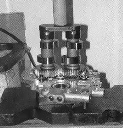
4. After lubing the ends of the cams, and aligning the timing marks, the cams are pressed into the bearings using the proper JIMS tool.
5. The S&S-supplied retaining ring can now be installed onto the end of the front cam using snap-ring pliers. Note that the chain tensioner shoes are removed from the cam support plate.
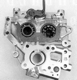
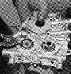
6. The assembled cam support plate assembly can now be slipped into the gearcase, with some lube on the ends of the cams.
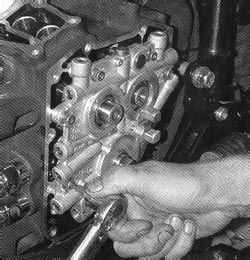
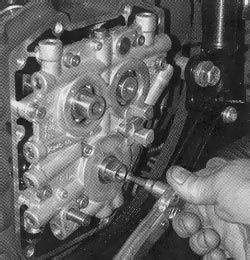
7. The support plate bolts are then torqued to spec, as per the sequence in the H-D manual, using a 3/16” Allen. The bolts are torqued to a final value of 105 in-lbs.
8. After using a 5/16” socket to install two Evo lifter block alignment pins to center the oil pump, Jamie installs the stock hardware using a 3/16” Allen on the oil pump bolts, which are torqued to 105 in-lbs. in a crisscross pattern.
9. He then removed the Evo alignment pins and installs the last two Allen bolts in the same was as the first two. This properly aligns and installs the oil pump.
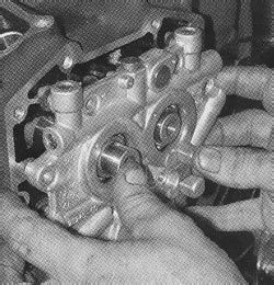
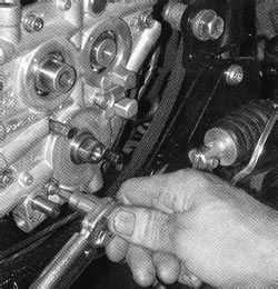
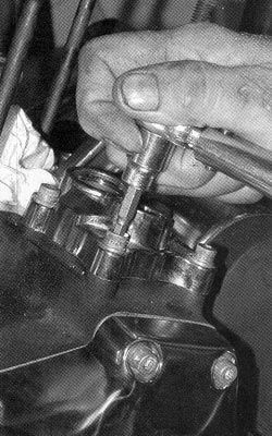
10. The S&S pinion drive gear can now be installed using the S&S bolt and washer, which are put in just fingertight for now. Be sure to align the dot on the gear with the line on the support plate.
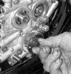
11. After the key is in place, the rear cam drive gear gets slipped over the rear cam’s protruding end. The S&S bolt and fat washer get installed just snug for now. Make sure that the alignment dots on both gears are lined up.
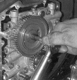
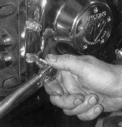
12. The pinion gear bolt is now torqued to 24 ft-lbs. using a 1/2” socket. The rear cam gear bolts get torqued to 34 ft-lbs. using a 5/16” Allen. Note: Both bolts should have red Loctite on their threads.
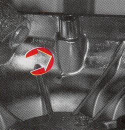
13. The inside face of the stock cam cover, by the top vertical bolt on the rear wall (arrow), is then clearanced to make room for the camshaft drive gears using a Dremel tool. Jimbo wants 0.045” between the gear teeth and the cover.
14. After cleaning the cover and installing a new gasket, Jimbo installs the cam cover. He uses a 3/16” Allen to torque the stock hardware to 105 in-lbs. as per the procedure in the H-D manual.
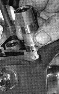
15. After putting some assembly lube in the lifter bores and on the lifter rollers, Jimbo drops the lifters into place in the case. Be sure you put the stock lifters back into their original holes.
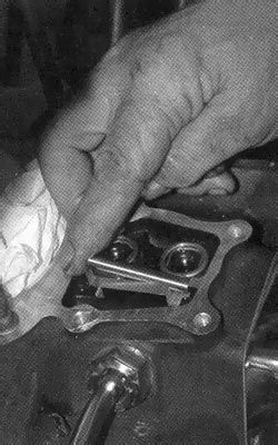
16. With the flat side of the lifters facing the flat wall in the case, Jimbo positions the alignment pin, which keeps the lifter’s roller aligned with the cam lobes, in the case as shown.
17. After a new gasket is positioned on the case, Jimbo reinstalls the lifter covers using a 3/16” Allen. He then torques the stock hardware to 105 in-lbs.
